Introduction
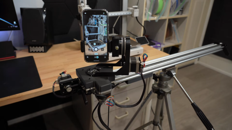
3D printers are built with modular, off-the-shelf components like extruded aluminum rails and stepper motors—perfect for repurposing. In this guide, we’ll walk you through constructing a three-axis camera slider, inspired by the work of [CNCDan], who used leftover printer parts to film his other projects. This how-to distills his experience, from motor upgrades to wireless control, into clear steps you can follow.

What You Need
Before starting, gather these materials and tools. Most can be salvaged from old 3D printers or purchased as common parts.
- Extruded aluminum rails (V-slot or similar, about 1–2 meters for the main axis)
- Stepper motors (NEMA 17 or similar, three units for X, Y, Z axes)
- Motor drivers (e.g., A4988 or TMC2209)
- Microcontroller (ESP32 recommended for wireless control)
- Steel or aluminum plate (for mounting camera carrier)
- Bearings (press-fit type, e.g., 608ZZ)
- Camera quick release plate (Arca-Swiss compatible)
- Timing belts and pulleys (GT2 or similar)
- Linear bearings or rollers (for smooth movement along rails)
- Power supply (12–24V, appropriate for motors)
- Wires, connectors, solder
- Tools: Drill, tap set, hex keys, screwdrivers, cutting tool (hacksaw or angle grinder), file, press (or hammer and block), multimeter
Numbered Steps
Step 1: Plan and Gather Parts
Assess what you have on hand from your 3D printer. Check that extruded rails are straight and free of debris. Measure the desired travel distance for each axis (typically 60–100 cm for the main slide). Determine gear ratios—CNCDan upgraded his motors for torque by adding reduction pulleys. Sketch a rough layout to avoid clearance issues later.
Step 2: Prepare the Base Rails
Cut two lengths of extruded aluminum for the main X-axis base. Tap the ends for mounting brackets or use T-nuts. Attach the rails parallel to each other, spaced to fit your linear bearings. Ensure they are level and square. For the Y and Z axes, shorter rail sections will ride on the carrier.
Step 3: Upgrade Motor Gear Ratios
Original 3D printer motors may lack sufficient torque for a heavy camera (1.4 kg). Increase gear ratio by using a small pulley on the motor and a larger one on the driven shaft—CNCDan used a 20-tooth to 60-tooth combo. This reduces speed but multiplies torque. Mount motors with custom brackets or 3D-printed holders. Test rotation and engagement of belts.
Step 4: Fabricate the Mounting Plate
Cut a steel (or thick aluminum) plate to serve as the camera carrier. Use the dimensions of your rails as guide. Drill holes for press-fitting bearings that will ride on the rails. CNCDan used a press to insert the bearings, but you can also tap them in with a hammer and a block. Sand edges smooth. This plate will also hold the quick release mechanism.
Step 5: Assemble the Carrier and Other Axes
Attach the mounting plate to linear bearings or rollers that slide on the X-axis rails. Then build the Y-axis (vertical) and Z-axis (pan) using smaller rail pieces. Stack them perpendicularly: the Y-axis rides on the X carriage, and the Z-axis on the Y carriage. Use belt tensioners to prevent slack. CNCDan found that gear ratio changes required him to rework these clearances, so double-check all dimensions as you go.
Step 6: Install the Quick Release Mechanism
Mount a standard Arca-Swiss compatible quick release plate onto the Z-axis. This allows fast attachment and removal of the camera. Ensure the plate is centered and securely fastened. Test with your camera or a dummy weight to balance the load.
Step 7: Wire the Electronics and Program the ESP32
Connect each stepper driver to the ESP32 (using GPIO pins for step, direction, enable). Provide 12–24V power to motors via the drivers. Write or upload custom driver code—CNCDan spent weeks refining acceleration and jerk profiles for smooth motion. Use the GitHub repository (provided by CNCDan) as a starting point. The code should handle three axes independently and accept commands via serial or Wi-Fi.
Step 8: Test Motion and Tune Parameters
With the camera (or a similarly weighted object) attached, run low-speed tests along each axis. Listen for grinding or stuttering; adjust microstepping, current limits, and acceleration values. CNCDan’s 1.4 kg camera required careful tuning to move smoothly without skipping steps. Use a GUI on a laptop to send test move commands.
Step 9: Implement Wireless Control
Leverage the ESP32’s Wi-Fi to create a web-based GUI. CNCDan controlled his slider from a separate computer on the same network. Alternatively, use an app like GRBL or ESP-3D. Program the interface to show live position, speed, and axis selection. This step makes the slider truly remote and versatile.
Step 10: Final Assembly and Calibration
Secure all wiring with zip ties, enclose electronics in a box, and check that belts are tensioned equally. Run a full sequence of moves—X, Y, Z individually and combined. Verify that the camera stays level and the image is steady. If vibrations occur, add damping pads under the base. Your three-axis camera slider is ready.
Tips
- Start with lighter loads: Test with a smartphone before mounting a heavy DSLR. This reduces risk of damage and makes tuning easier.
- Use existing parts first: Repurposing 3D printer parts saves money, but be prepared for iterative modifications (as CNCDan did). Steel plates may need replacement after gear changes.
- Document your code: Comment the driver code thoroughly; future tweaks will be simpler. Share improvements on GitHub to help the community.
- Consider alternative uses: A camera slider can also serve for time-lapse, product photography, or high-speed video when combined with a high-frame-rate camera (see related projects).
- Check bearing alignment: Slight misalignment can cause binding. Use machinist’s square to verify at each step.